by Dave Williamson – – –
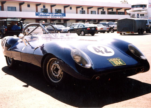
John Murn and I had been discussing the state of the motor in his 1960 Decca sports car. While being a solid power plant and having the reputation for being reliable, the trusty English 1500 BMC “B” series motor has its own Achilles heel: its weight. Part of the reason is that it has a very heavy flywheel and clutch assembly, which led to owners being plagued with a spate of broken crankshafts.
The reason for these breakages first needs explaining. In the 1950s, both Jack Brabham and Kiwi driver Len Gilbert ran Cooper Bristol racing cars. When Len bought his car from UK owner Horace Gould, it came as a surprise when Gould commented: “Be aware that these motors do break crankshafts!”
Here in Australia, Jack had also heard about this. During motor rebuilds, both he and Len quickly discovered the reason for the breakages. When the motors were stripped down, the simple act of removing the flywheel required a world champion weightlifter! Unnecessarily large and far too heavy, they were breaking crankshafts for one simple reason. As the cars raced, the massive flywheel had to suddenly rev up, then slow down, then spin back up again.
This continuous violent twisting motion put tremendous strain on the rear section of the crankshaft – which protested by simply breaking.
Having good engineering backgrounds, both Jack and Les wisely machined their flywheels in their lathes, removing a huge amount of weight. This lightening action soon prevented any more breakages from occurring.
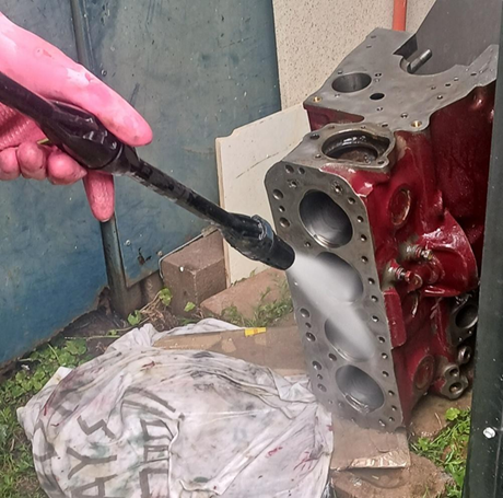
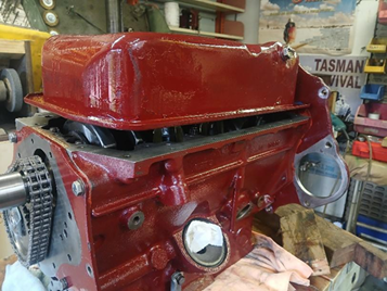
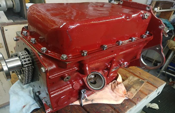
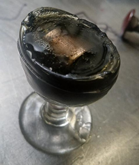
John had decided to remove the cylinder head to see how the motor had survived the 20 years since it had been built. Visible at the top of the cyl. bores was a large amount of oil.
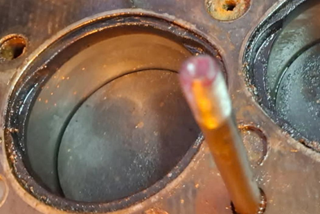
This created a challenge. How and where did the oil come from? The bores provided a possible clue, as some of the original criss-cross honing patterns were still visible! This indicated the possibility that the piston rings may never had “bedded in” totally. One reason possible for that is when the motor was assembled 20 years ago, the camshaft may have been liberally coated in a graphite grease, to help the bedding in procedure for the camshaft lobes.
Sometimes this will add to the engine oil and then create a super-slippery film on the wall of the cylinder bores, which can prevent proper bedding-in of the piston rings.
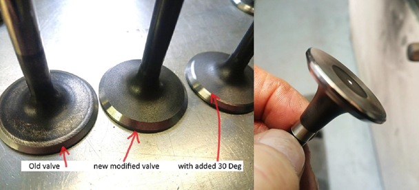
The next area to check were the valve guides. If they are excessively worn, inlet guides allow oil to be vacuumed down past the valves and enter the combustion chamber. This “extra” oil reduces the octane rating of the fuel, greatly reducing the power output of the motor and creating lots of carbon and black oily deposits. New guides were fitted including new valve stem seals. Some valves also showed wear, so the decision was made to get a new set. Easier said than done. With no history of the part numbers of these items, I had to do a long Internet hunt. I finally discovered they were modified Holden V8-288 valves. I modified the faces on the inlet valves by adding a 30 deg. angle to the faces, to improve the inlet flow. I also rounded the edges of the top of the exhaust valves to improve exhaust gas flow.
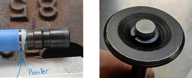
Although the new valves were the correct length, they required a different type of collet groove to be machined into each valve. I put paint onto the stem of each valve and made a simple device with a short pointer, so as to mark where the new collet groove must go. I then cut the new grooves – the hard valve material was very difficult to machine.
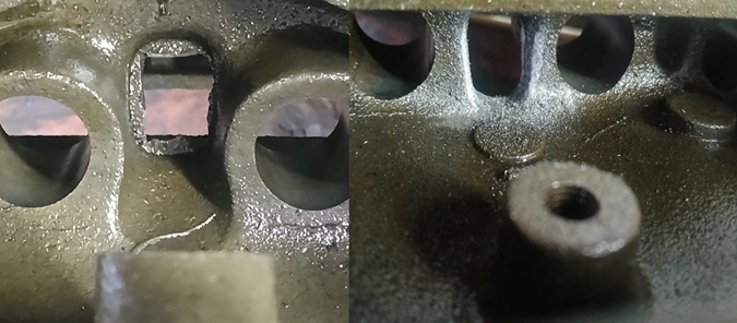
The valve seat areas in the cylinder head were not in good condition. When doing an initial “test cut”, severe corrosion was visible in many of the seats.
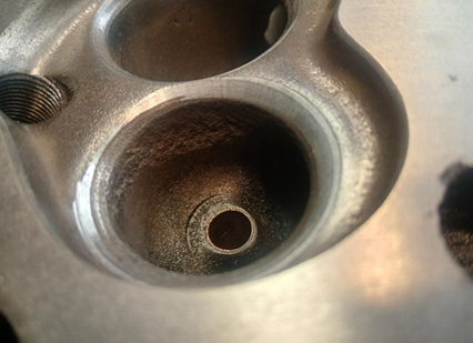
New valve seat inserts could have been fitted, but the BMC B series heads are thin in this area and are prone to exposing the water jacket if machined deeply, so larger exhaust valves were used and the problem was solved.
The rocker assembly was stripped and checked, the rocker shaft showing severe wear, so a new one was ordered.
The rocker pads were worn so I polished them.
Amazingly, deep grinding marks were evident on each rocker.
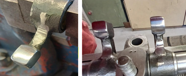
Such deep marks qualify as classic “stress risers”, ie. areas where cracks can easily originate. To minimise this situation, I polished out the grind marks.
This is an important area to focus on, as the rockers are made from chilled cast iron and whilst strong, they can be brittle.
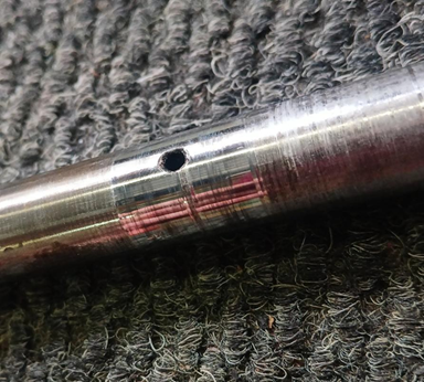
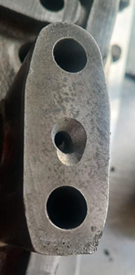
The position of the outlet feedhole (from the oil gallery to the head) was questionable. I found the feed holes were misaligned and so required modification to ensure a 100% oil feed.
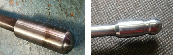
The previous motor builder had lengthened the pushrods, done by adding extension pieces to the pushrods. This increased the reciprocating weight – which spells trouble for a valve train. I lightened each one by machining in a groove and tapering one end.
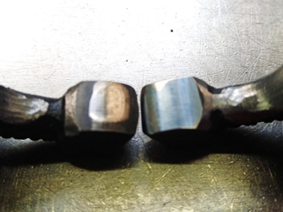
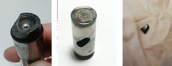
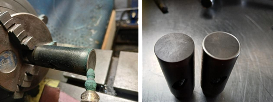
I felt that a look at the cam followers would be a good thing. Glad we did, as we we found some that were badly scuffed, with one cracked at the top.
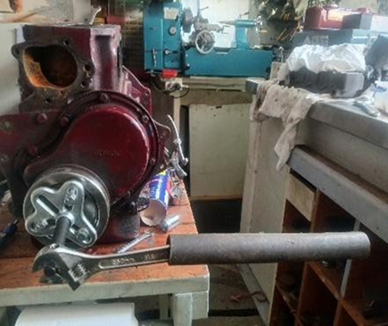
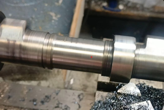
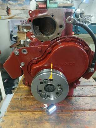
That there was obviously some stray metal floating around inside the motor was cause enough to decide to remove the motor from the car and strip it right down. This process began by removing the front pulley. It had been installed using Loctite and simply would not come off. After fitting a stronger puller, plus an extension tube, plus WD40, I left it to sit overnight. In the morning I used even more force on the puller… and BANG! off it came.
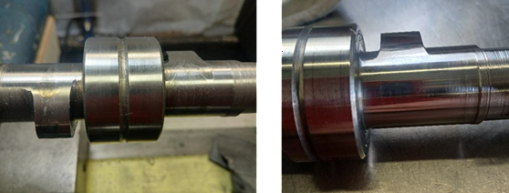
The camshaft showed scoring on many of the lobes. I removed the scores by polishing the lobes in my lathe.
The bores and the pistons were in good shape. Surprisingly, there was still some small evidence of honing marks – after 20 years! This showed that the rings had not totally bedded in. One reason might have been: that excess graphite grease was put onto the camshaft (during the previous assembly) and this had mixed with the engine oil and prevented creating the normal ring-to-bore surface-finish.
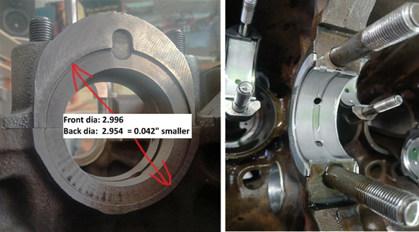
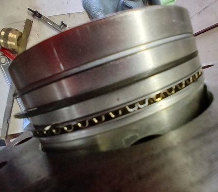
The mains, big ends, thrust and cam bearings were all scored. Locating correct replacement parts meant a lot of “hunting” time on the Internet. I found that the thrust bearing faces in the block were different sizes, with a difference of 0.042” – which then required re-sizing the O/D of the rear two washers to fit.
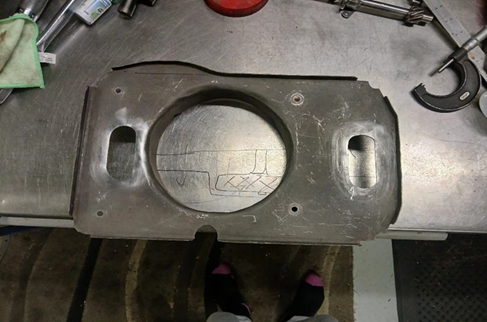
Surprised to see that the No 1 and No 4 conrods had previously been scraping on each end of the sump, so someone had used a hammer to create some clearance!
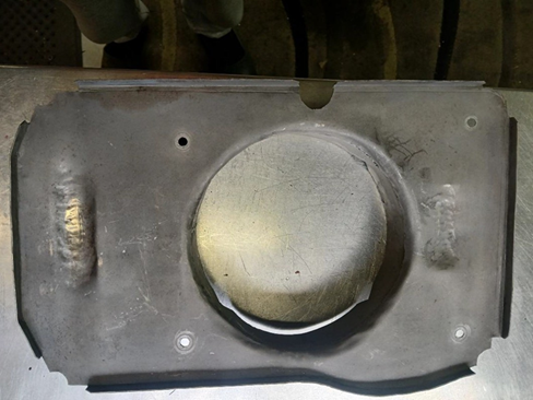
I felt this was a potential problem in the future, so I created two slots to enable oil to return more quickly back into the sump.
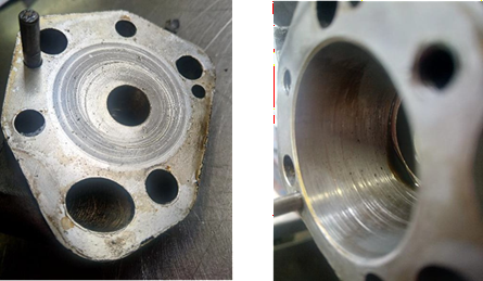
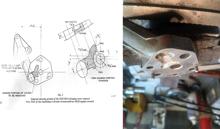
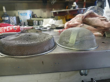
The oil pump was scored on both the ID and the end plate. A new pump was obtained and a modification undertaken to increase input to the pump. This required hand cutting off the end plate.
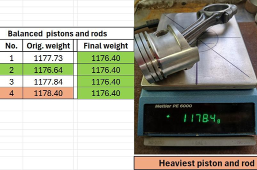
When the total weight of both rods and pistons was checked, a difference of two grams was measured. The heaviest was 1178.40 and the lightest 1176.40 grams, so they were all re-balanced to 1176.40 grams.
The car runs an electric fuel pump, so there is no need to have an eccentric fuel pump lobe left on the camshaft. This will unbalance the camshaft and motor, so I removed the lobe in the lathe.
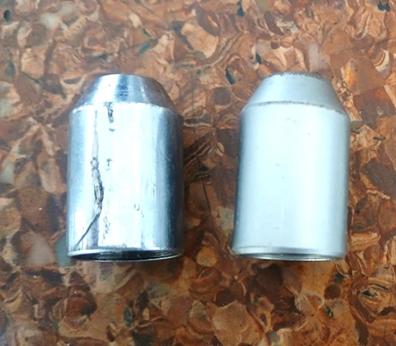
The oil pressure relief valve piston was cracked. It could stick and fail to regulate oil pressure – so it was replaced.
Casting “flash” around the oil drain-back holes slows down the oil return back down to the sump. I smoothed the area around these holes to improve flow.
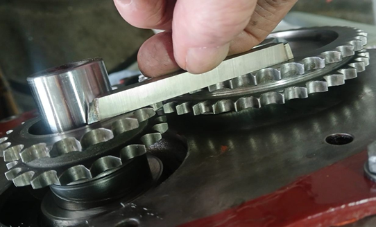
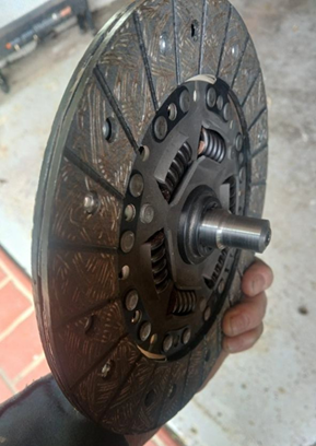
The flywheel still had rough grinding marks on the friction surface. I used the lathe to polish out the marks.
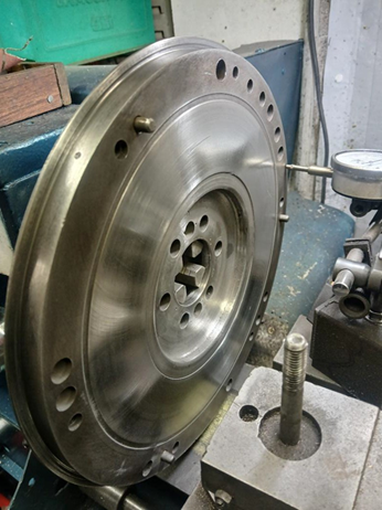
A new ring gear was also fitted, using oxy-acetylene to generate heat to enable the correct expansion amount for the ring gear to fit onto the flywheel.
The pistons were non-standard, creating a real challenge to source the correct piston rings. These were found to be the same type as used in a Suzuki Swift G13-B motor… but 0.020” oversize… certainly not a BMC part!
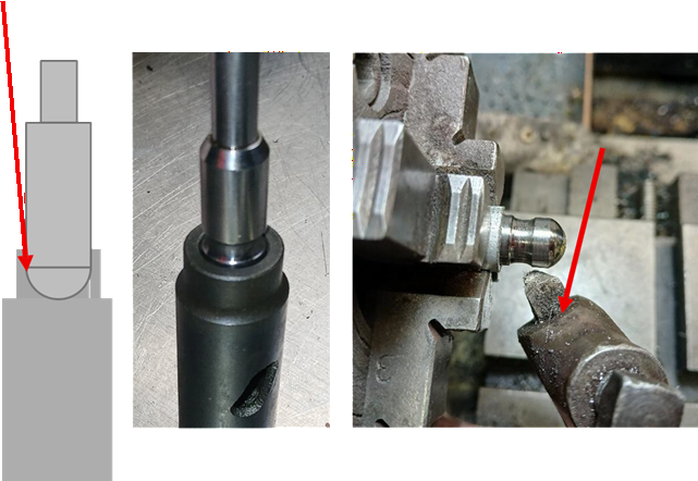
Detective work was used to understand how one cam follower had broken. When checking the pushrods, one was found to be nearly .010” thou larger than the others. This would mean the ball-end was too tight inside the top of the cam follower, which put pressure around the thin edge.
On checking the rocker and valve setup, it was observed that 6 mm thick shims had been fitted underneath the rocker pedestals. Using non-standard valves, these were necessary to achieve the correct geometry. At 50% lift, there should be a reference line from the ball-end of the pushrod, then through the centre line of the rocker shaft, to the top of the valve.
The crankshaft is a fabulous SAINTY product, created by a brilliant Sydney engineer – the late Stan Sainty. Stronger than the original BMC crank, it had been fitted to reduce the chance of future crankshaft breakages.
The new cam followers had very sharp edges -not good on original cam lobes. I used a fine polishing stone to radius the edges.
Removing the worn spigot bush was interesting, as I used an old trick I learnt during my apprenticeship days. I filled the spigot bush with bread, then used a “dummy shaft” to hammer the bread into the bush. With nowhere to go, the compressed bread slowly forced the old bush out.
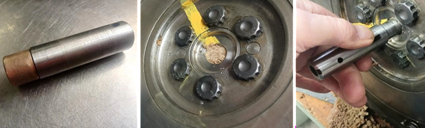
I soaked the new sintered-bronze bush in a mixture of engine oil and graphite overnight.
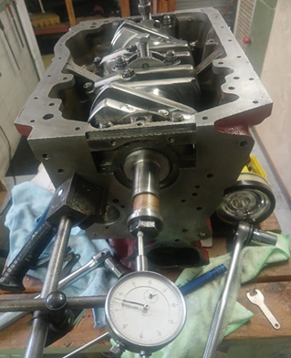
To ensure 100% alignment when mounting the clutch pressure plate onto the flywheel, I used the dummy shaft.
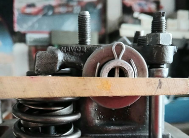
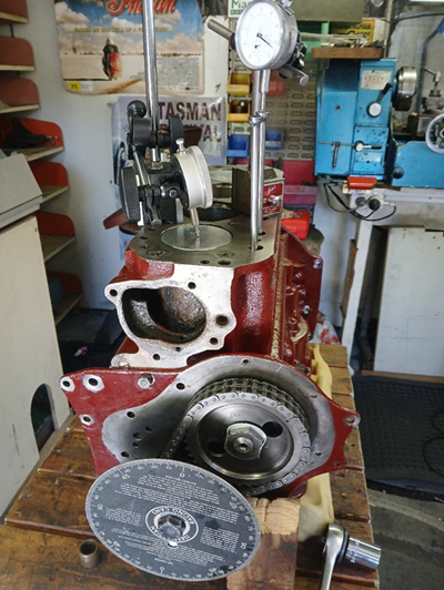
Two timing marks were created. One: to show Top Dead Centre (TDC), and the other: to indicate ignition timing of 30 deg. before TDC.
There are more things to write about in this story, however this will be enough for now!
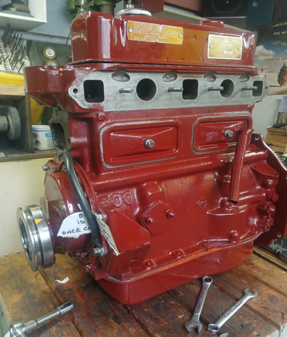
The motor is now ready to be fitted back into the car.
(If you missed part 1 of the Decca Major story, by John Murn, read it here)